Design and Simulation of Fir Filter Using Vhdl
FIR Filter Introduction
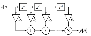
Finite Impulse Response (FIR) filters are characterized by a time response depending only on a given number of the last samples of the input signal. For a causal discrete-time FIR filter of order N, each value of the output sequence is a weighted sum of the most recent input values:

where:
- x[n] is the input signal,
- y[n] is the output signal,
- N is the filter order; a Nth-order filter has (N+1) terms on the right-hand side
- bi is the value of the impulse response at the i'th instant for 0<= i <=N of a Nth-order FIR filter. If the filter is a direct form FIR filter then is also a coefficient of the filter (see Figure1).
This computation is also known as discrete convolution.
On Wikipedia FIR web-page, you can find further information on FIR design theory.
FIR Filter Hardware Architecture
Here we want to see how to implement FIR filter architecture in FPGA or ASIC using VHDL.
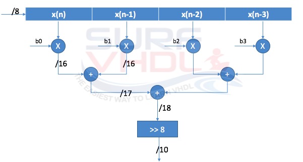
Figure 2 reports an example of 4 taps FIR direct form that can be simply coded in VHDL. In figure 2, the input x(n) and the coefficient bi are 8-bits signed.
After the filter coefficients multiplication, the multiplier output dynamic will be an 8+8=16 bit.
In fact, when you multiply two numbers of N-bit and M-bit the output dynamic of the multiplication result is (N+M)-bits.
When you perform addition, the number of bit of the result will be incremented by 1. The FIR filter design architecture of figure 2 can be easily extended to a length greater than 4.
FIR Filter Design VHDL Code
Here below is reported the VHDL code for the FIR filter design of figure 2. The VHDL code implements a low pass FIR filter with 4 taps, 8-bit input, 8-bit coefficient.
library ieee; use ieee.std_logic_1164.all; use ieee.numeric_std.all; entity fir_filter_4 is port ( i_clk : in std_logic; i_rstb : in std_logic; -- coefficient i_coeff_0 : in std_logic_vector( 7 downto 0); i_coeff_1 : in std_logic_vector( 7 downto 0); i_coeff_2 : in std_logic_vector( 7 downto 0); i_coeff_3 : in std_logic_vector( 7 downto 0); -- data input i_data : in std_logic_vector( 7 downto 0); -- filtered data o_data : out std_logic_vector( 9 downto 0)); end fir_filter_4; architecture rtl of fir_filter_4 is type t_data_pipe is array (0 to 3) of signed(7 downto 0); type t_coeff is array (0 to 3) of signed(7 downto 0); type t_mult is array (0 to 3) of signed(15 downto 0); type t_add_st0 is array (0 to 1) of signed(15+1 downto 0); signal r_coeff : t_coeff ; signal p_data : t_data_pipe; signal r_mult : t_mult; signal r_add_st0 : t_add_st0; signal r_add_st1 : signed(15+2 downto 0); begin p_input : process (i_rstb,i_clk) begin if(i_rstb='0') then p_data <= (others=>(others=>'0')); r_coeff <= (others=>(others=>'0')); elsif(rising_edge(i_clk)) then p_data <= signed(i_data)&p_data(0 to p_data'length-2); r_coeff(0) <= signed(i_coeff_0); r_coeff(1) <= signed(i_coeff_1); r_coeff(2) <= signed(i_coeff_2); r_coeff(3) <= signed(i_coeff_3); end if; end process p_input; p_mult : process (i_rstb,i_clk) begin if(i_rstb='0') then r_mult <= (others=>(others=>'0')); elsif(rising_edge(i_clk)) then for k in 0 to 3 loop r_mult(k) <= p_data(k) * r_coeff(k); end loop; end if; end process p_mult; p_add_st0 : process (i_rstb,i_clk) begin if(i_rstb='0') then r_add_st0 <= (others=>(others=>'0')); elsif(rising_edge(i_clk)) then for k in 0 to 1 loop r_add_st0(k) <= resize(r_mult(2*k),17) + resize(r_mult(2*k+1),17); end loop; end if; end process p_add_st0; p_add_st1 : process (i_rstb,i_clk) begin if(i_rstb='0') then r_add_st1 <= (others=>'0'); elsif(rising_edge(i_clk)) then r_add_st1 <= resize(r_add_st0(0),18) + resize(r_add_st0(1),18); end if; end process p_add_st1; p_output : process (i_rstb,i_clk) begin if(i_rstb='0') then o_data <= (others=>'0'); elsif(rising_edge(i_clk)) then o_data <= std_logic_vector(r_add_st1(17 downto 8)); end if; end process p_output; end rtl;
The FIR filter is implemented fully pipelined, in fact, there is a registration stage at the output of each multiplication or addition.
The output dynamic of the FIR filter is 10-bit, i.e. is not fully dynamic output.
The VHDL code of the FIR filter can be implemented either in ASIC or in FPGA. The implementation should be guarantee full speed for the FIR filter.
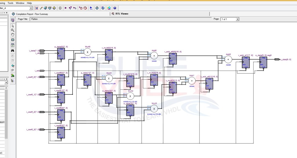
Figure 3 shows RTL viewer of Altera Quartus II for the FIR filter VHLD example code above
If you appreciated this post, please help us to share it with your friend.
If you need to contact us, please write to: surf.vhdl@gmail.com
We appreciate any of your comment, please post below:
Design and Simulation of Fir Filter Using Vhdl
Source: https://surf-vhdl.com/how-to-implement-fir-filter-in-vhdl/
0 Response to "Design and Simulation of Fir Filter Using Vhdl"
Postar um comentário